Inductively Coupled Plasma Modeling
- Sina Alavi
Due to the various applications of ICP, investigating the effects of various phenomena on characteristics and performance of ICP through experimental and numerical methods is of great utility. In addition to optical spectrometry which is an indispensible technique for plasma diagnostics, in CACT we also benefit from powerful 2D and 3D numerical models which have been developed based on more than 30 years of experience. These models are capable of simulating the electromagnetic fields, heat transfer, fluid flow, and species concentration inside the ICP as well as its interaction with solid particles and sample droplets.
Methodology
To simulate the ICP, we solve the Navier-Stokes and energy equations in a 2D axisymmetric domain using the ANSYS-FLUENT software. The ideal gas fluid flow is considered to be laminar, in a steady state, and Newtonian. The plasma is also considered to be in local thermal equilibrium (LTE) condition, optically thin, and with global charge neutrality. The Maxwell equations are added to FLUENT, in the form of user-defined functions and scalars, and solved based on the vector potential method to obtain the electric field intensity, magnetic flux density, and current density throughout the computational domain. Based on these results, the values of Lorentz forces and Joule heating can be calculated and substituted into the Navier Stokes and energy equations to account for the effects of the electromagnetic field on fluid flow and heat transfer inside the ICP torch. In addition, the species transport equation is included in the model to account for the effects of the surrounding air on the argon plasma as well as water vapor generated due to sample droplets. Injection of droplets was accomplished using the discrete phase model.
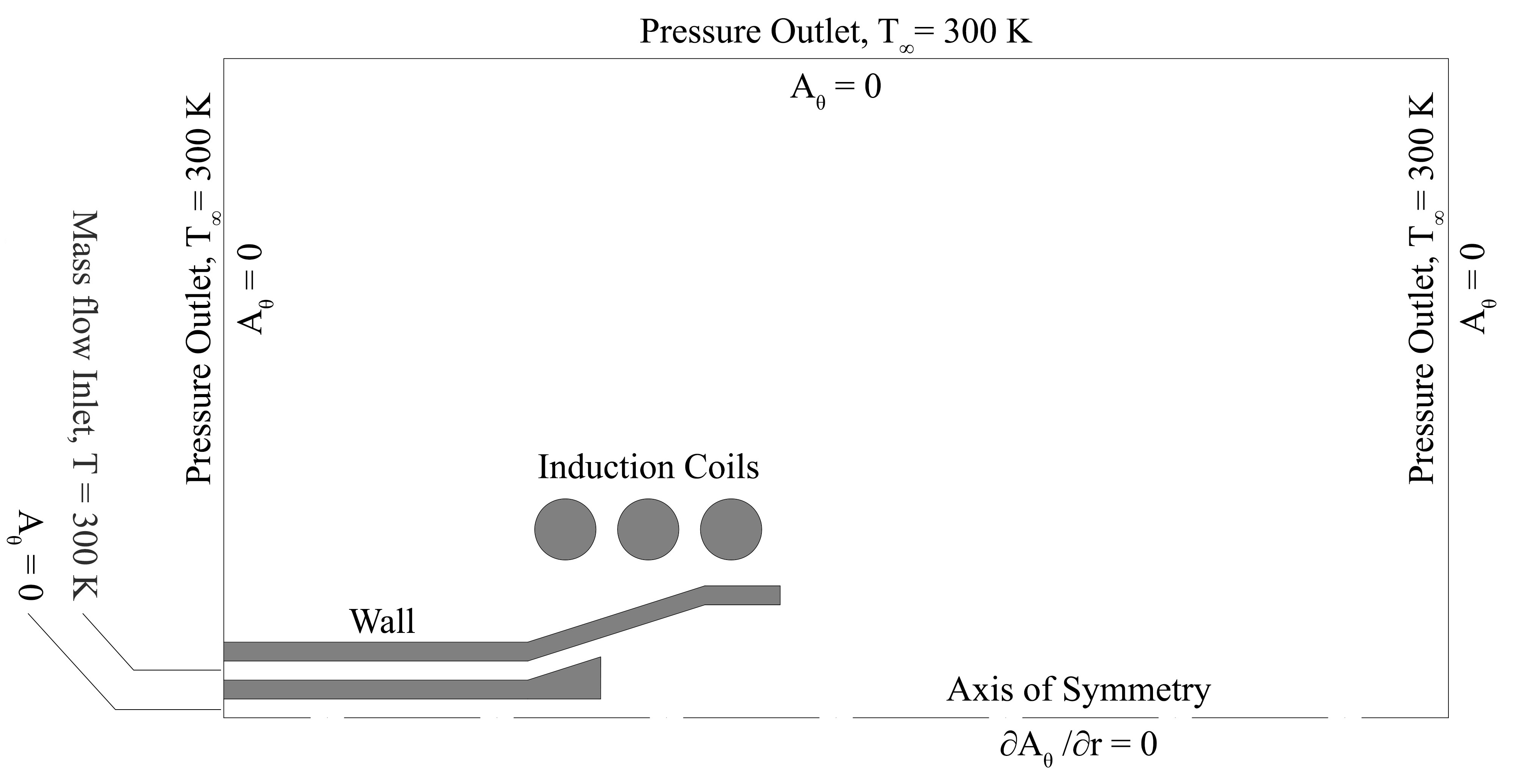
Schematics of the 2D axisymmetric computational domain and boundary conditions
Comparison between the New Conical Torch and the Conventional Fassel Torch
The figure on the right shows the results of simulations for the new conical torch (developed in CACT) and the conventional Fassel torch at various flow rates. It can be seen that the energy induction zone for the conical torch is smaller compared to the Fassel torch. For case (f), the volume of the induction zone is calculated to be ~ 1230 mm3. For the conical torch, the volume of the induction zone is around 330 mm3. Therefore, the power density inside the conical torch would be about 4 times higher in comparison to the Fassel torch.
At the same flow rate and power of 8 L/min and 1000 W, the plasma inside the conical torch (case d) is about 1000 K higher compared to the Fassel torch (case e). On the other hand, simulations show that, for the same 8 L/min flow rate, the average velocity of the outer gas in the conical torch is ~ 10 m/s in comparison to ~ 3 m/s for the Fassel torch. In other words, the conical design has led to a > 3-time improvement in the cooling efficiency of the outer gas. Therefore, even for a flow rate as low as 6 L/min (case-b) the maximum temperature on the outer tube was obtained to be around 540 K which is well below the allowable working temperatures of quartz . At such a low flow rate, the plasma would be very unstable inside the Fassel torch. This was indeed observed in both the simulations and experiments.
Using the discrete phase model, 5 μm water droplets were injected to the plasma at a rate of 20 μL/min. As shown in the figure below, the simulations could predict the droplet trajectories, size change, and evaporation due to interaction with the plasma. For the conical torch with 1 mm injector tube (0.5 L/min carrier gas), the whole phenomena leading to excitation of species is predicted to take only ~ 510 μs to complete. For the Fassel torch with a 1 mm injector tube (0.5 L/min carrier gas), the same time was estimated to be ~ 1060 μs which is more than twice compared to that of the new torch. For the new torch, the longest time was obtained to be ~ 1550 μs for the 2 mm injector tube (0.9 L/min carrier gas). For the same injector size of 2 mm (1 L/min carrier gas), the Fassel torch exhibited a residence time of 2550 μs. The superiority of the new conical torch in this aspect is due to localization of energy inside the plasma which leads to better physical parameters of the plasma. Therefore, it can be concluded that the conical torch is capable of ionizing/exciting sample species at least 2 times faster than the Fassel torch with the same injector I.D.
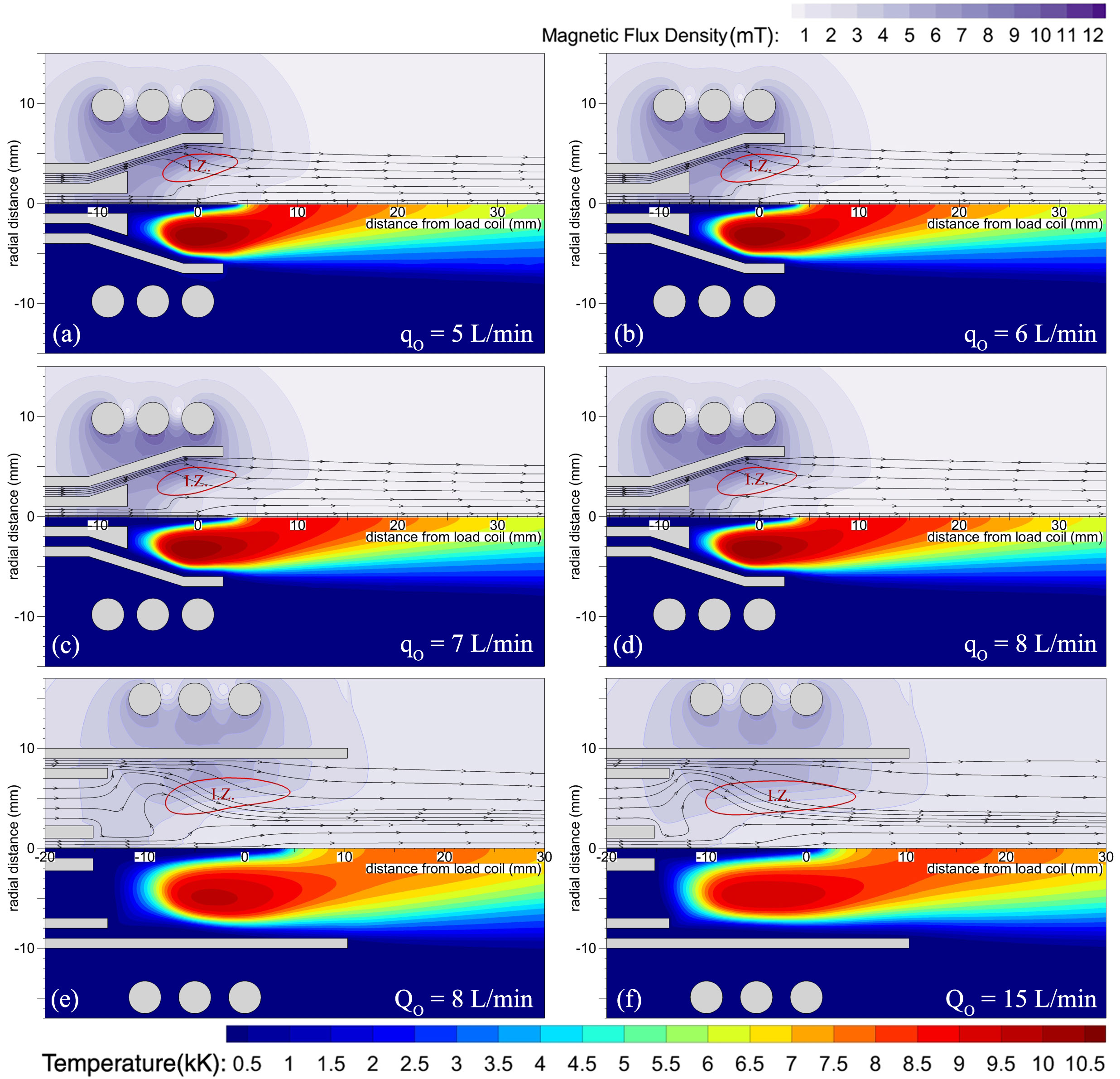
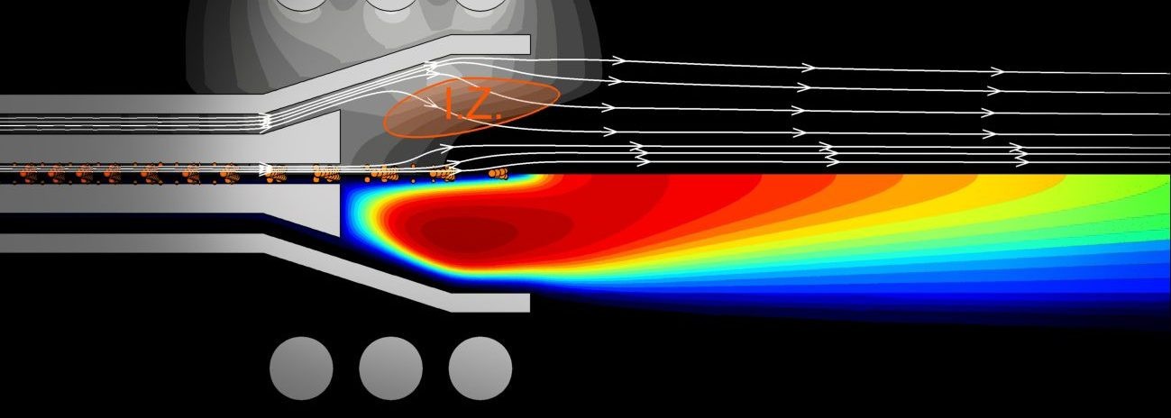
Computer-simulated temperature (bottom), magnetic flux density (top) and streamlines inside the new (a, b, c, d) and Fassel (e, f) torches for various outer gas flow rates. Power, intermediate gas (only for the Fassel torch), and carrier gas flow rates were set to 1000W, 1 L/min, and 1 L/min, respectively. The boundary of the induction zone (I.Z.) is determined based on 1/e of the maximum current density in the plasma (Plasma Chem. Plasma Process., 2019, 1-18).
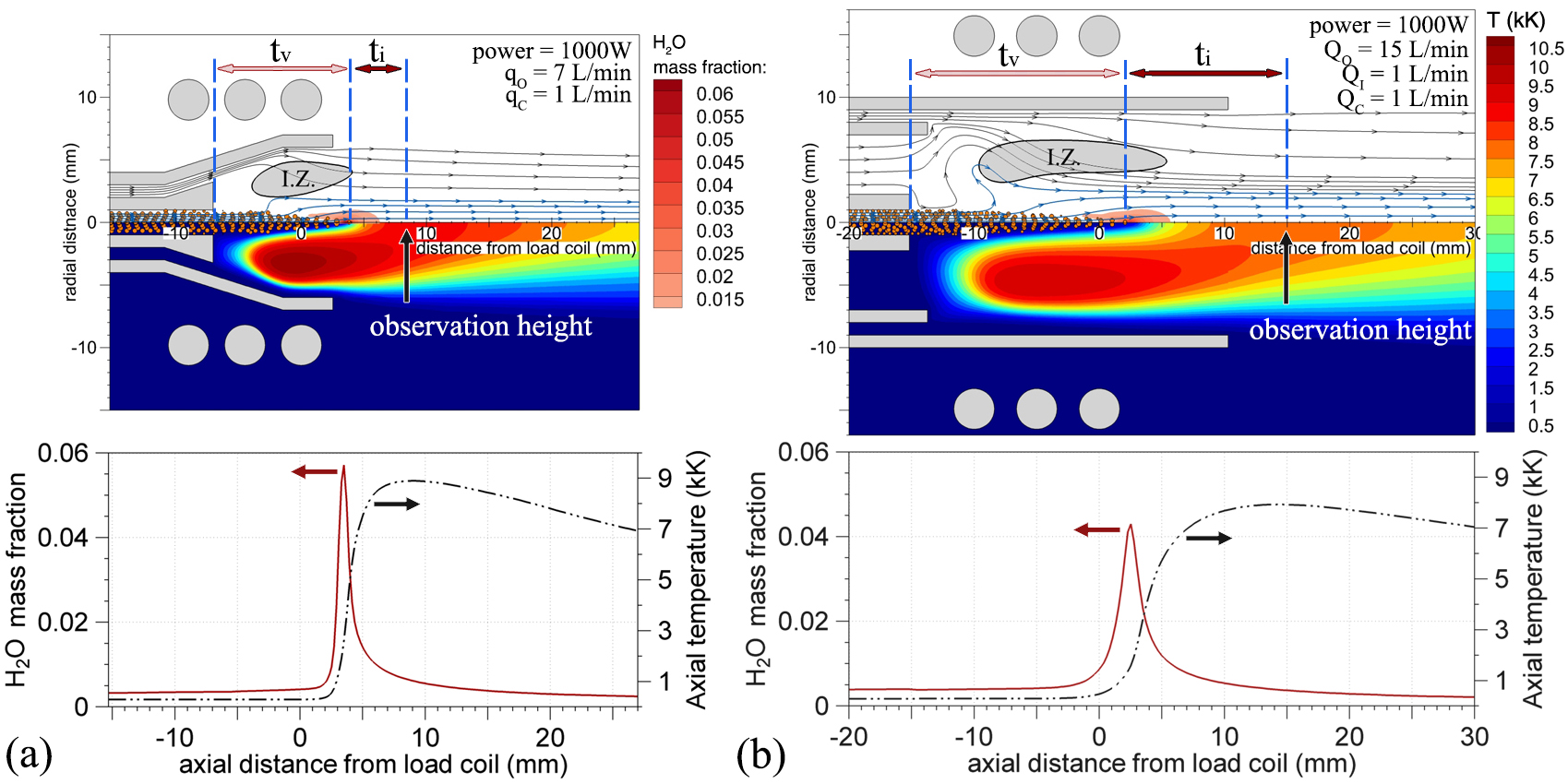
(Top) computer simulated distribution of water vapor mass fraction, temperature, water droplet trajectories, and streamlines for the (a) conical and (b) Fassel torches. The boundary of the induction zone (I.Z.) is determined based on 1/e of the maximum current density in the plasma. (Bottom) axial variations of water vapor mass fraction and temperature (Plasma Chem. Plasma Process., 2019, 1-18).